

Calculate boiler feedwater flow, required pump head, design flow, hydraulic power, shaft power and estimated motor power.
A boiler feed pump is an important part of a boiler water system because it supplies feedwater to the boiler at the required pressure and flow rate. Selecting an appropriate pump requires more than choosing one based on boiler steam production. Feedwater flow, boiler pressure, static elevation, piping losses, design margins, pump efficiency, and motor efficiency can all affect the required pump duty.
Our Boiler Feed Pump Calculator provides a preliminary estimate of the main pump requirements. It calculates the required feedwater flow, design pump flow, pressure head, total design head, hydraulic power, shaft power, motor input power, and an indicative standard motor size.
This calculator is intended for preliminary engineering estimation and educational use. Always check the final pump selection against the actual system design and the pump manufacturer’s performance data.
“This calculator provides a preliminary boiler feed pump duty estimate only. It is not a substitute for detailed engineering design or manufacturer-certified pump selection.”
A boiler feed pump delivers water to a boiler or steam-generation system. Because the water must enter the boiler against system pressure, the pump must produce sufficient pressure and flow.
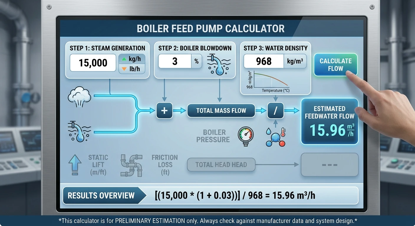
The required pump duty depends on the operating conditions of the boiler and feedwater system.
Some important factors include:
The Boiler Feed Pump Calculator brings these basic inputs together to produce an initial estimate.
The calculator provides several useful engineering estimates:
These values can help you understand the approximate duty that a boiler feed pump may need to handle.
However, the calculator does not replace a detailed hydraulic analysis or manufacturer pump selection.
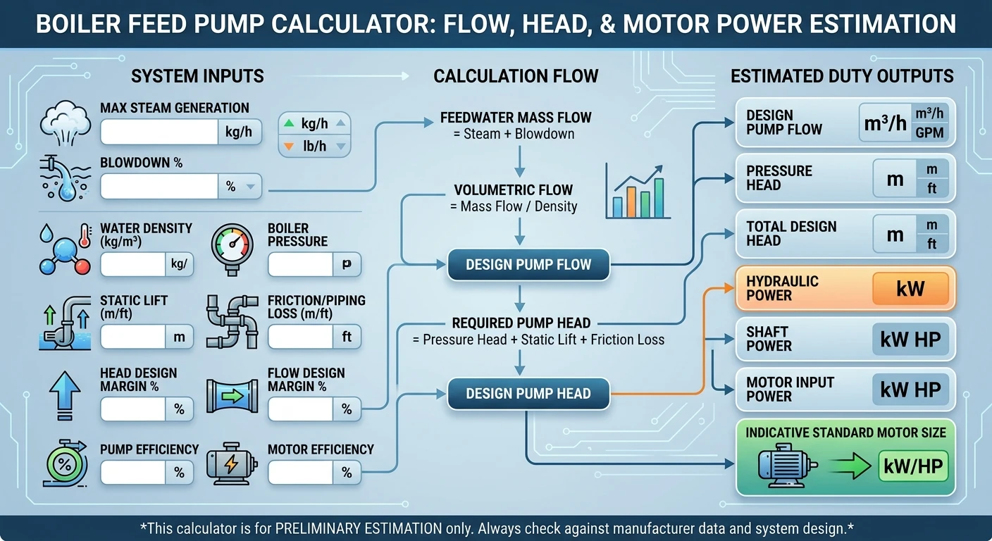
Enter the maximum steam generation rate of the boiler.
The calculator supports:
For example, you might enter:
15,000 kg/h
When you select the imperial unit, the calculator converts pounds per hour to kilograms per hour.
Enter the blowdown percentage.
For example: 3%
Boiler blowdown represents water removed from the boiler to control dissolved solids and other water-quality-related conditions.
For this calculator, the feedwater requirement is estimated using:
Feedwater mass flow = Steam flow + Blowdown flow
The calculator determines blowdown flow as
Blowdown flow = Steam generation × Blowdown percentage
For example, with a steam generation rate of 15,000 kg/h and 3% blowdown:
Blowdown = 15,000 × 0.03
Blowdown = 450 kg/h
The estimated feedwater requirement would therefore be
15,000 + 450 = 15,450 kg/h
This is a simplified calculation and does not account for every possible water source or destination in a real boiler system.
Enter the feedwater density in kg/m³.
The calculator uses 968 kg/m³ as its default example value.
Water density varies with temperature, so select the actual feedwater density based on the system’s operating conditions.
The calculator converts mass flow into volumetric flow using:
Volumetric flow = Mass flow / Density
For example, if feedwater mass flow is 15,450 kg/h and density is 968 kg/m³:
Flow ≈ 15.96 m³/h
The actual result will depend on the values entered.
The Boiler Feed Pump Calculator estimates the required flow rate, pump head, hydraulic power, and motor power. You can also use our Percentage Calculator for blowdown rates, efficiency, and design margins.
Pump head represents the energy per unit weight the pump must add to the fluid. In practical pump calculations, head is commonly expressed in meters or feet of fluid.
For a boiler feed pump, the required head can include several components.
The calculator considers:
The preliminary calculation is
Required head = Pressure head + Static lift + Friction loss
A design margin is then applied to the calculated head.
The calculator converts boiler pressure into an equivalent water head.
For pressure entered in bar, it uses the relationship between pressure, fluid density, and gravitational acceleration.
The basic relationship is
H = P / (ρ × g)
Where:
If you enter pressure in psi, the calculator first converts it to pascals and then calculates the equivalent head.
Carefully define the pressure used in a real pump-head calculation. Depending on the system, you may need to distinguish between gauge pressure, absolute pressure, and the pressure difference between suction and discharge.
Therefore, treat the result from this calculator as a preliminary estimate rather than a final pump specification.
Static lift represents the vertical elevation difference that the pump must overcome.
The calculator allows static lift to be entered in:
Feet are converted to meters using the standard conversion:
1 ft = 0.3048 m
For example:
10 ft × 0.3048 = 3.048 m
Static elevation can significantly affect the total required head, particularly in systems where the boiler and feedwater equipment are at different elevations.
Water flowing through pipes, valves, fittings, heat exchangers, and other components experiences pressure losses.
The calculator allows you to enter an estimated friction/piping loss.
This value is added to the pressure head and static lift to estimate the required pump head.
In a detailed engineering design, you should normally calculate friction loss from the actual piping arrangement, pipe diameter, length, fittings, valves, flow velocity, and fluid properties.
The calculator does not independently calculate loss for each pipe and fitting.
The calculator includes a Head Design Margin (% input.
For example, if the calculated required head is 100 m and a 10% design margin is entered:
Design head = 100 × 1.10
Design head = 110 m
This input lets the user apply a preliminary design allowance.
The appropriate margin depends on the engineering design and should not be selected arbitrarily for a final installation.
The calculator also provides a flow design margin.
If the calculated feedwater flow is 20 m³/h and the design flow margin is 10%:
Design flow = 20 × 1.10
Design flow = 22 m³/h
This provides an estimated design flow for the preliminary pump duty.
A final system should use the actual operating and design requirements rather than relying only on a generic percentage margin.
After determining design flow and design head, the calculator estimates the pump’s required hydraulic power.
The hydraulic power relationship used is
P = ρ × g × Q × H
Where:
Because the calculator receives flow in m³/h, it converts the flow to m³/s before calculating hydraulic power.
The result is then displayed in kilowatts.
Hydraulic power represents the theoretical power transferred to the fluid.
It does not represent the electrical power the motor requires because real pumps are not 100% efficient.
For example, if a system requires a certain hydraulic power and the pump operates at 72% efficiency, the shaft power must be higher than the hydraulic power.
The calculator estimates shaft power using:
Shaft power = Hydraulic power / Pump efficiency
If pump efficiency is 72%, it is entered as:
0.72
For example, if hydraulic power were 10 kW:
Shaft power = 10 / 0.72
Shaft power ≈ 13.89 kW
The actual pump efficiency depends on the selected pump, operating point, speed, impeller configuration, and other factors.
The calculator then accounts for motor efficiency.
The relationship used is
Motor input power = Shaft power / Motor efficiency
If motor efficiency is 93%, it is represented as
0.93
For example, if shaft power were 13.89 kW:
Motor input power ≈ 13.89 / 0.93
Motor input power ≈ 14.94 kW
The calculator also converts motor power to horsepower for reference.
The calculator compares the estimated motor input power with a predefined list of standard motor sizes.
It then displays the first listed motor size that is equal to or greater than the calculated motor input power.
For example, if the estimated motor input requirement is approximately 14.9 kW, the calculator may show:
15 kW
This is an indicative standard motor size only.
Do not interpret it as a final motor selection.
Actual motor selection may depend on:
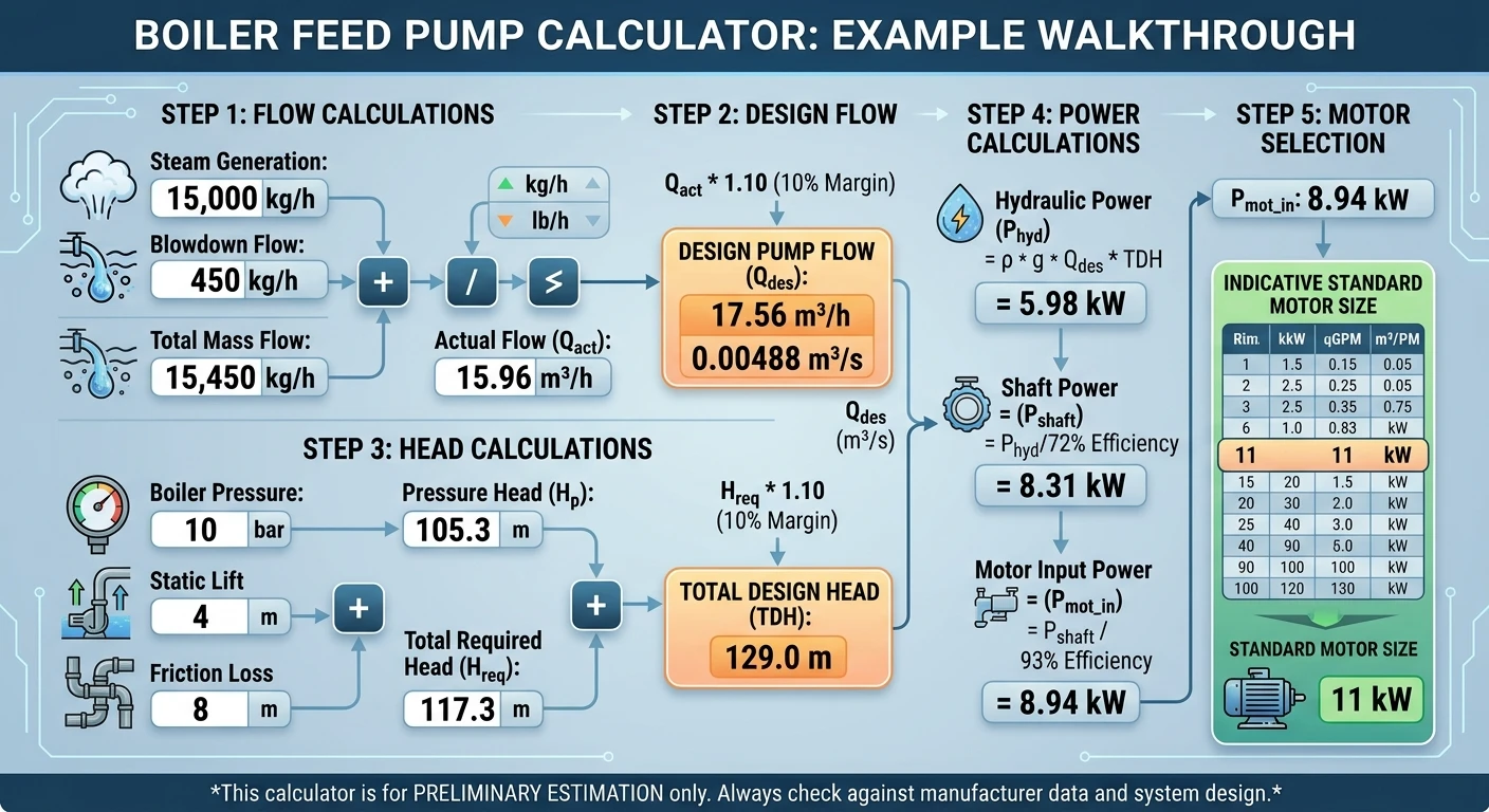
Consider a hypothetical system with:
The calculator first estimates the blowdown flow:
15,000 × 3% = 450 kg/h
Feedwater mass flow becomes approximately:
15,450 kg/h
The corresponding volumetric flow is approximately
15,450 / 968 ≈ 15.96 m³/h
The calculator then converts boiler pressure into pressure head and adds static lift and piping losses.
Finally, it applies flow and head margins before calculating hydraulic power, shaft power, and motor input power.
Because this example involves engineering assumptions, use it only to understand the calculation process. A real boiler installation requires actual equipment and system data.
Pump efficiency directly affects the required shaft power.
A more efficient pump can deliver the required hydraulic duty with less shaft power than a less efficient pump under comparable conditions.
For this reason, pump selection should consider the pump’s performance curve rather than simply selecting a pump based on its maximum rated flow or head.
Check the desired operating point against the manufacturer’s published pump curve.
Motor efficiency affects the electrical input required to produce the pump’s required shaft power.
If motor efficiency decreases, the electrical input required for the same shaft output increases.
This is why the calculator includes motor efficiency separately from pump efficiency.
You should not treat the two efficiencies as the same thing.
The calculator provides a simplified preliminary estimate. It does not perform a complete boiler-feedwater system design.
It does not independently calculate:
These factors matter when designing an actual boiler feedwater system.
NPSH, or Net Positive Suction Head, is an important consideration in pump applications.
A pump can experience performance problems or cavitation if the available suction conditions don’t meet the pump’s requirements.
The calculator does not calculate NPSHa or compare it with the manufacturer’s NPSHr.
For an actual boiler feed pump installation, evaluate suction pressure, feedwater temperature, tank elevation, piping losses, pump location, and other system conditions.
A pump’s rated maximum flow and maximum head do not tell the complete story.
Manufacturers provide pump curves showing how the pump performs at different flow rates and heads.
When selecting a pump, check the design operating point against the appropriate pump curve.
Also evaluate the pump for efficiency, NPSHr, minimum continuous stable flow, and other manufacturer specifications.
A boiler feed pump supplies feedwater to a boiler or steam-generation system at the pressure and flow the system requires.
A simplified approach is to estimate feedwater flow from steam generation plus applicable blowdown:
Feedwater = Steam generation + Blowdown
The actual water balance of a complete boiler system may include additional considerations.
A preliminary pump-head estimate can include pressure head, static lift, and piping/friction losses:
Required head = Pressure head + Static lift + Friction loss
You may then apply a design allowance based on the engineering basis.
Hydraulic power is the power the pump transfers to the fluid. It can be estimated using:
P = ρgQH
where density, flow, gravity, and head determine the required hydraulic power.
Shaft power can be estimated by dividing hydraulic power by pump efficiency:
Shaft power = Hydraulic power / Pump efficiency
The calculator estimates motor input power by dividing shaft power by motor efficiency:
Motor input power = Shaft power / Motor efficiency
No. It provides a preliminary duty estimate. Final pump selection requires manufacturer pump curves and detailed system information.
No. This tool does not calculate NPSHa or NPSHr; check those separately for an actual pump installation.
Density is needed to convert mass flow into volumetric flow and to convert pressure into an equivalent fluid head.
Because water density varies with temperature, the value used should represent the actual operating conditions as closely as possible.
Yes. The calculator accepts steam flow in kg/h or lb/h, pressure in bar or psi, and static lift/friction values in meters or feet.
No. The displayed standard motor size is only an indicative result based on the calculated motor input power. Final motor selection requires engineering review and equipment-specific information.
The Boiler Feed Pump Calculator provides a convenient starting point for estimating boiler feedwater flow, pump head, hydraulic power, shaft power, and motor input power.
The calculation begins with steam generation and blowdown, converts the resulting feedwater mass flow into volumetric flow, estimates pressure head and system losses, applies design margins, and then calculates the approximate power requirement.
For educational purposes and preliminary planning, these calculations can help explain the relationship between boiler capacity, pump flow, pump head, and motor power.
For an actual boiler installation, however, a qualified engineer should review the calculated values and check them against the manufacturer’s pump curves, NPSH requirements, system piping, operating temperatures, pressure conditions, applicable standards, and boiler-system requirements.
This Boiler Feed Pump Calculator provides a preliminary engineering estimate for feedwater flow, pump head, hydraulic power, shaft power, and indicative motor power. The results are intended for educational and preliminary sizing purposes only.
Actual boiler feed pump selection depends on site-specific operating conditions and equipment data. Before selecting or purchasing a pump, verify the required flow and head against the manufacturer’s pump curve, and check NPSH available (NPSHa), NPSH required (NPSHr), feedwater temperature, suction conditions, piping and valve losses, minimum-flow requirements, control-valve pressure drop, boiler operating pressure, and applicable codes or regulations. NPSH and suction arrangement are particularly important because inadequate suction conditions can lead to cavitation and pump damage.
This calculator does not replace a detailed engineering design, manufacturer-certified selection, or professional engineering review. Do not use the calculated motor size as the sole basis for equipment procurement or safety-critical decisions.

Zain Bin Shabbir is a content creator and website publisher with 2 years of experience in SEO, web content, and practical online tools. He focuses on creating clear, useful, and user-friendly resources that simplify everyday calculations.
Guides that go deeper into this topic